L293d Motor Driver Circuit Diagram Pdf
This project is a DC motor driver, suitable for motors of low or medium power. Allows controlling up to 6 motors or 3 motors if you want to control the rotation of the motors. Description The controller is build around the IC L293D that can provide 600mA per channel, and a H-Bridge designed with transistors NPN and PNP transistors, than can provide 1.15A per channel. The controller has the following connections: • INPUTS (A, B, C, D,E, F). These are receiving the analog or digital signals that can be sent for example, from a microcontroller. • ENABLE (E1-2, E3-4).
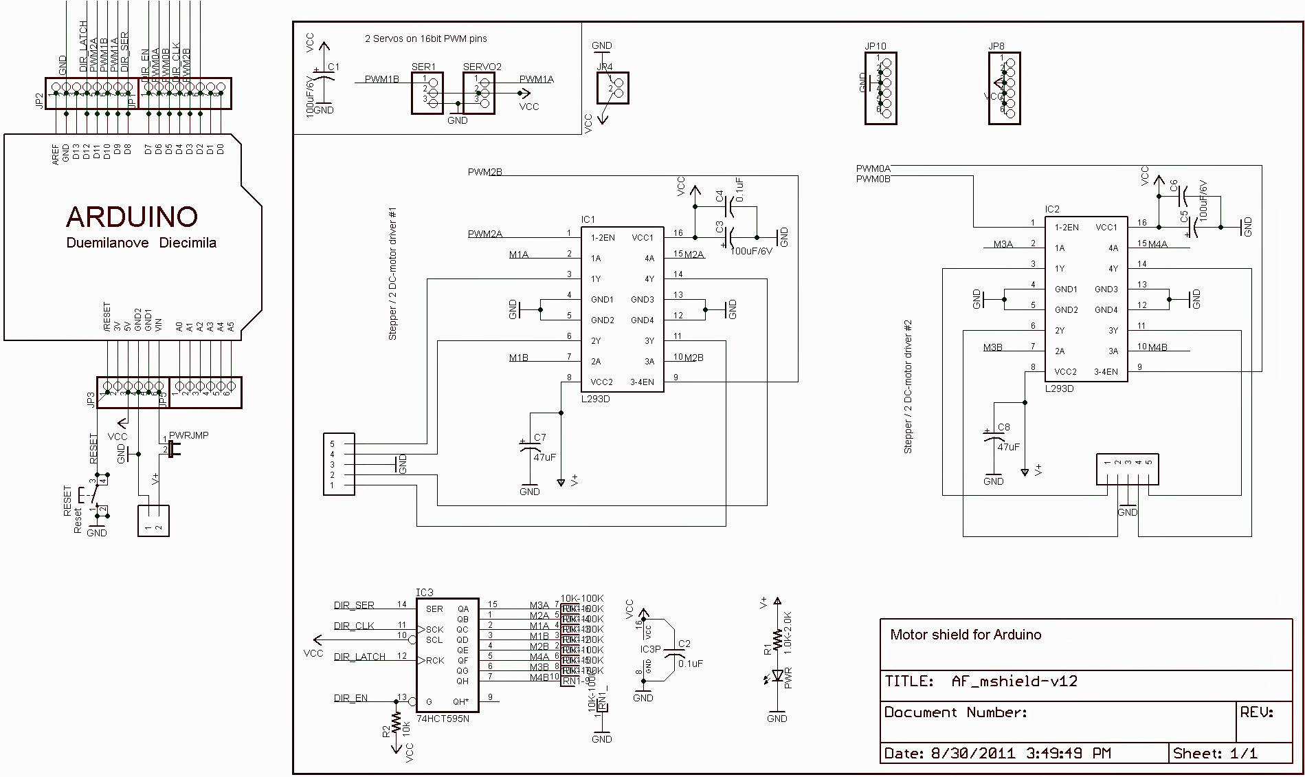
The L293D driver has 2 VCCs: VCC1 is +5V and VCC2 is +12V (same as motor nominal voltage). Pins IN1 and IN2 are the control pins where: As shown in the circuit diagram we need only 3 Arduino terminal pins, pin 8 is for the push button which toggles the motor direction of rotation.
These activate the inputs from the L293D. The supply voltage can’t be higher than 7V. • OUTPUTS (+M1, -M1, +M2, -M2, +M3, -M3). Here is where the motors should be connected.
Here’s where is connected a supply voltage that will give power to the motors. This input, gives voltage in the L293D and the H-Bridge, the supplied voltage have to be 36V max, but for the H-Bridge it’s recommendable to use 24V max.
(In case you want to use only the L293D, you can remove the jumper). This input receive the logic supply voltage for the L293D.
You can connect a supply voltage higher than 5V because this input it’s connected to a voltage regulator (LM7805), but you not must to exceed 30V. Schematic Connections PCB 3D PCB.
A motor driver is an integrated circuit chip which is usually used to control motors in autonomous robots. Motor driver act as an interface between Arduino and the motors.
The most commonly used motor driver IC’s are from the L293 series such as L293D, L293NE, etc. These ICs are designed to control 2 DC motors simultaneously. L293D consist of two H-bridge. H-bridge is the simplest circuit for controlling a low current rated motor. We will be referring the motor driver IC as L293D only. L293D has 16 pins. The L293D is a 16 pin IC, with eight pins, on each side, dedicated to the controlling of a motor.
There are 2 INPUT pins, 2 OUTPUT pins and 1 ENABLE pin for each motor. L293D consist of two H-bridge. H-bridge is the simplest circuit for controlling a low current rated motor. - Pin Characteristics • 1 - Enable 1-2, when this is HIGH the left part of the IC will work and when it is low the left part won’t work.• 2 - INPUT 1, when this pin is HIGH the current will flow though output 1• 3 - OUTPUT 1, this pin should be connected to one of the terminal of motor• 4,5 - GND, ground pins• 6 - OUTPUT 2, this pin should be connected to one of the terminal of motor• 7 - INPUT 2, when this pin is HIGH the current will flow though output 2• 8 - VCC2, this is the voltage which will be supplied to the motor. • 16 - VCC1, this is the power source to the IC. So, this pin should be supplied with 5 V• 15 - INPUT 4, when this pin is HIGH the current will flow though output 4• 14 - OUTPUT 4, this pin should be connected to one of the terminal of motor• 13,12 - GND, ground pins• 11 - OUTPUT 3, this pin should be connected to one of the terminal of motor• 10 - INPUT 3, when this pin is HIGH the current will flow though output 3• 9 - Enable 3-4, when this is HIGH the right part of the IC will work and when it is low the right part won’t work.
Why 4 grounds in the IC? The motor driver IC deals with heavy currents. Due to so much current flow the IC gets heated.
Download doraemon episodes in hindi highly compressed free. Hello friends welcome to INDIAN ANDROID GAMER, I am sahil and I have Brought to you a very special video with the best gaming features, a graphics and the latest content of Action. This game was personally compressed by me for you all guys out there, this amazing game has came to you all your androids you guys are definitely gonna love it 😉😉😉 FEEDBACK WILL BE APPRECIATED ORIGINAL SIZE OF GAME: approx.
So, we need a heat sink to reduce the heating. Therefore, there are 4 ground pins. When we solder the pins on PCB, we get a huge metalllic area between the grounds where the heat can be released. Why Capacitors? The DC motor is an inductive load. So, it develops a back EMF when supplied by a voltage. There can be fluctuations of voltage while using the motor say when suddenly we take a reverse while the motor was moving in some direction.

At this point the fluctuation in voltage is quite high and this can damage the IC. Thus, we use four capacitors that help to dampen the extreme variation in current.
- пятница 08 марта
- 1